Rendering grid-based "Fog of War" in Unreal Engine 4 (Part 1)
In this article I'll document a solution for a grid-based fog of war. In part 1 I'll go over this rather traditional technique used in RTS games to perform fog of war. In Part 2 I'll go over how I handled this for multiple floors.
The solution is engine-agnostic, however I'll be using my game, which uses Unreal Engine 4, as the starting point for demonstration. This article will assume you know the basics of programming and some light knowledge of shaders.
BTW this solution is definitely not original and there are many implementations out there. I've combed through the internet not finding any useful literature about this, so I'm writing here to share knowledge so you don't have to figure it out on your own.
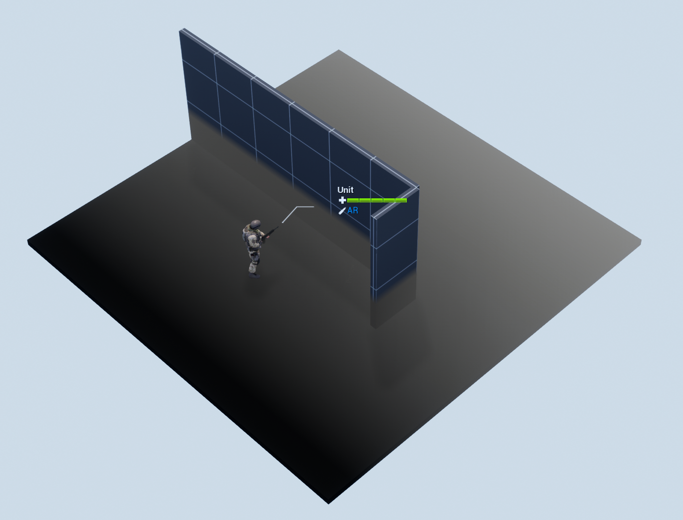
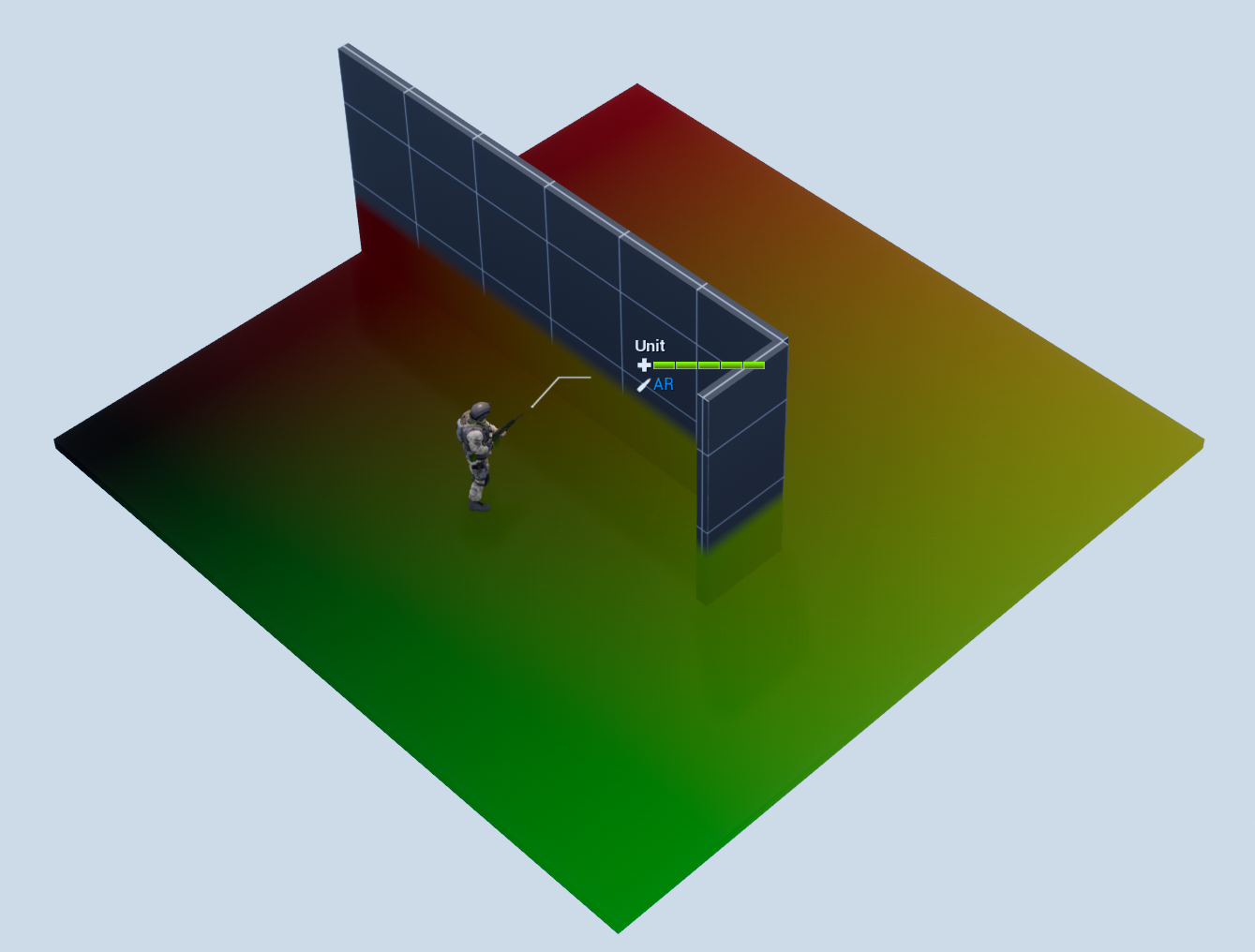
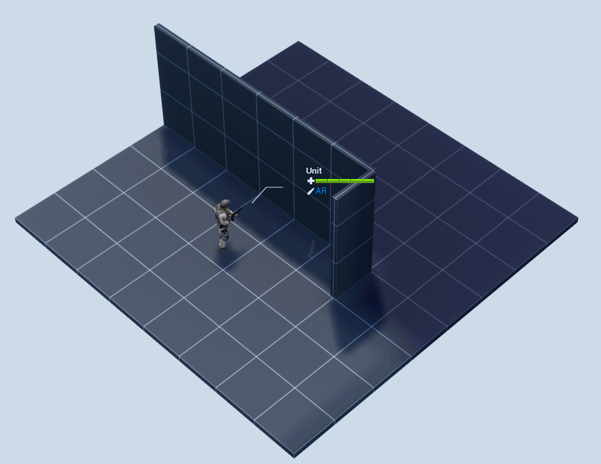
This is the effect we are going to try and achieve:
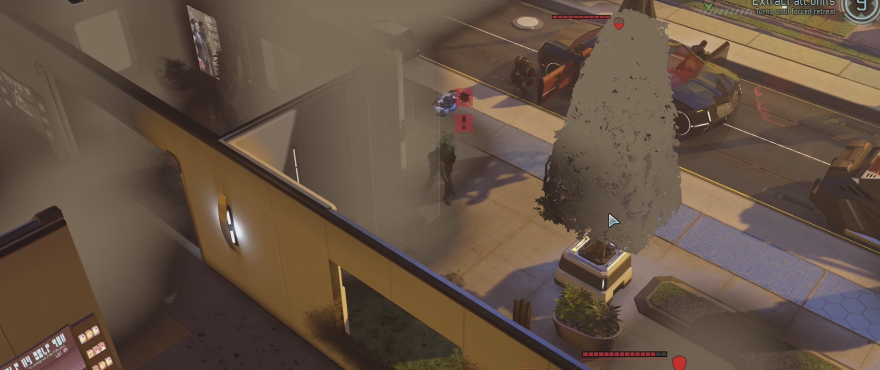
In XCOM 2, the fog of war covers non visible areas, however the player is still able to see through it and gleam overall shape of the map. We won't be getting into multiple elevations in this article, that will be in the next part. For now let's just focus on getting it to work in two dimensions.
Some Assumptions
- Your game world's visibility calculation can be divided into grid cells: volumes of space that are either visible or not visible.
- You've already done line of sight calculation in your game. This article won't go over this for you. It will focus purely on the rendering aspect.
- We want a solution that is art-pipeline-agnostic. This means we don't want to modify *any* art assets in our environment just to make this effect work.
- We're doing this in Blueprint. You could just as easily do this in C++, my project and demo is just in BP.
My game uses the excellent Advanced Turn Based Tile Toolkit framework which gives me the 3D grid which this demonstration will work off of. If you're making a turn based, grid based game, I highly recommend it.
The Setup
This type of fog of war is pretty typical for real time strategy games and mini-maps.
- Write each visible cell into a single pixel to a canvas.
- Display this canvas as decal material.
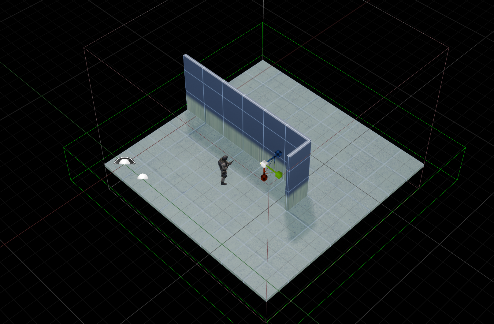
Really simple! Here's what an example map looks like.
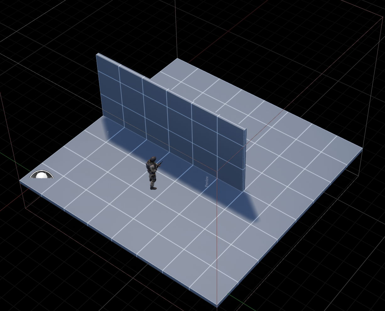
Again, let's assume you've already done the work of solving for each tile's visibility (say, through raycasting).
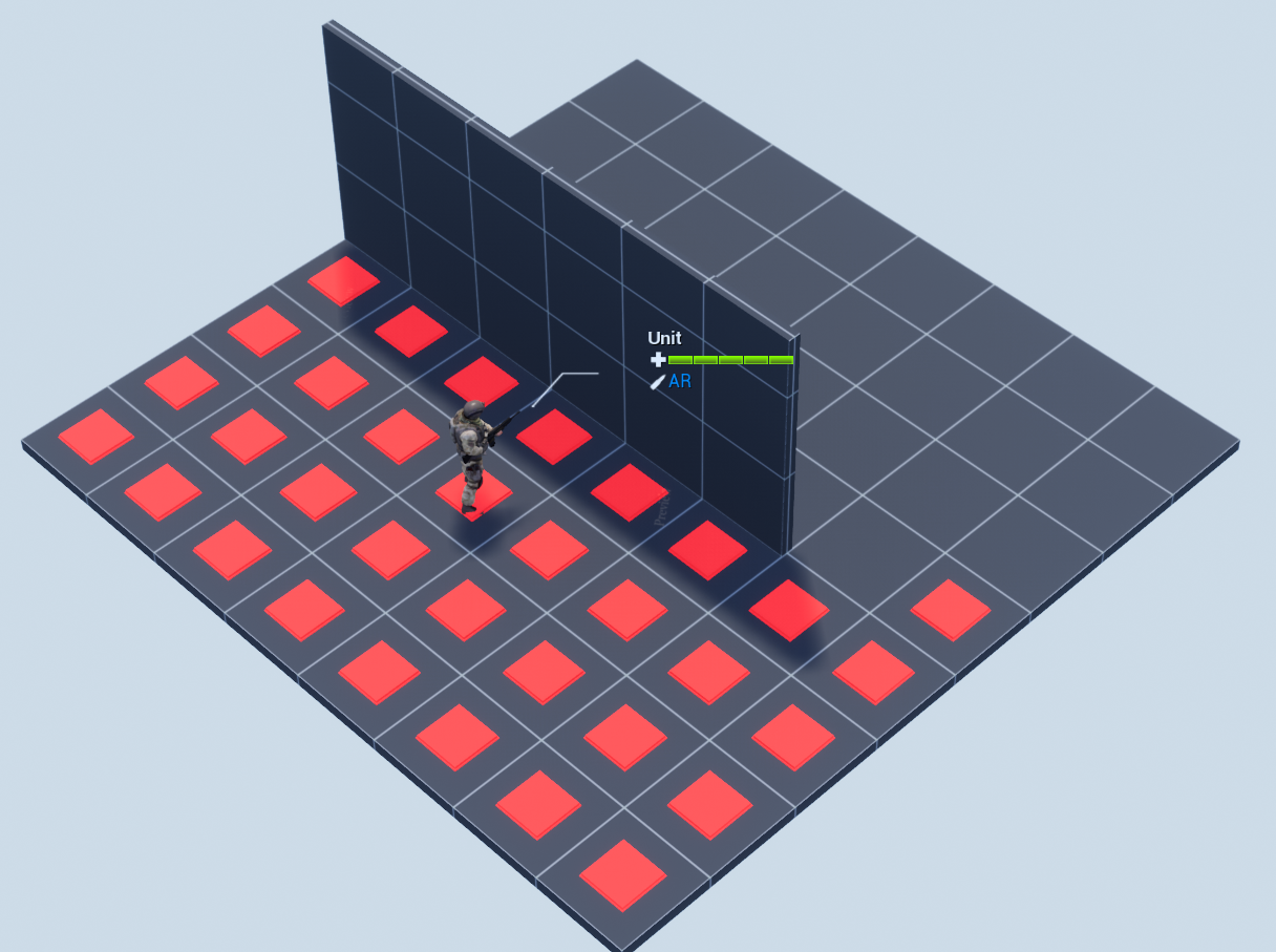
Each red square marks a visible tile to the unit.
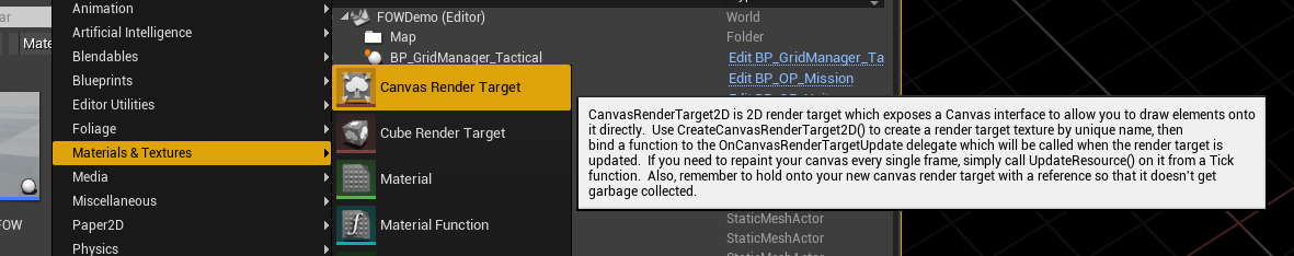
Canvas Render Target
We want a black and white texture dynamically generated, with the visible tiles white and everything else black. To do this, we create a canvas and draw into it.
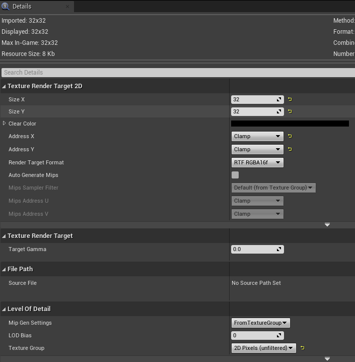
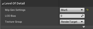
It's important to set the width and height correctly. Here one pixel represents a single tile in grid space, so we want the image to be at least as big. In this demo I've chosen 32, which would effectively make my maps 32 tiles wide maximum.
Note that we want to clamp the texture lookup, rather than wrap or mirror. For testing purposes, we also want the Mip setting to be 2D Pixels (unfiltered) so we can see sharp edges as we work.
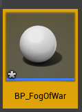
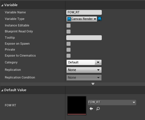
Next we need an actor to perform updates on this. In this demo I'll just make a BP fog of war class and add it to the scene. It will have a member variable FOW_RT which holds a reference to this canvas. (Note that you can also make this canvas dynamically instead of as an asset, this is just one way to do it).
Fog of war Blueprint
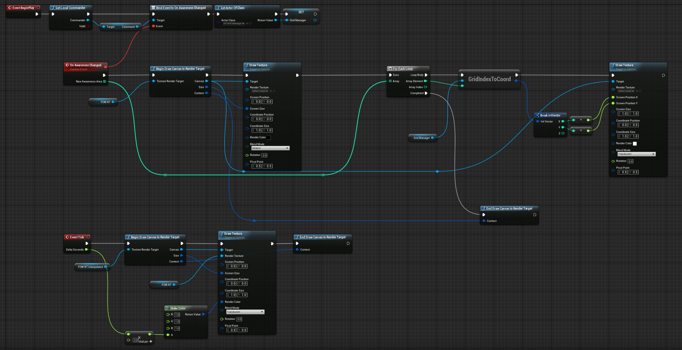
In my game, I have an event dispatcher that fires every time the visibility of my controlled units change. This is where you'll need to figure out how to hook this up in your game.
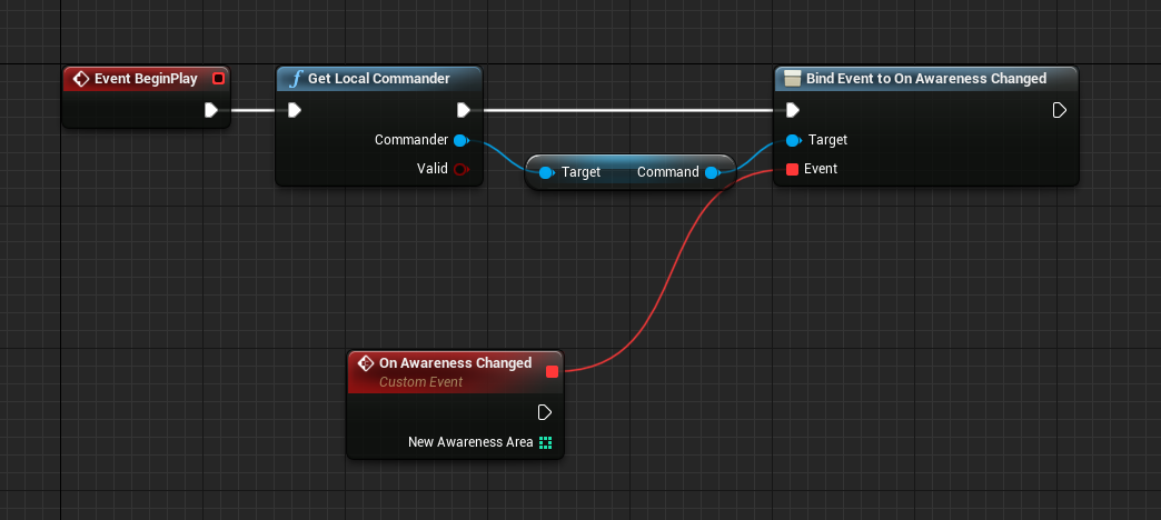
Here, the int array represent tile indexes. You can represent 2D locations with a single integer, so long as you have the grid width size. Essentially the index = x + y * width. You can always reverse the calculation and get the X and Y from an index.
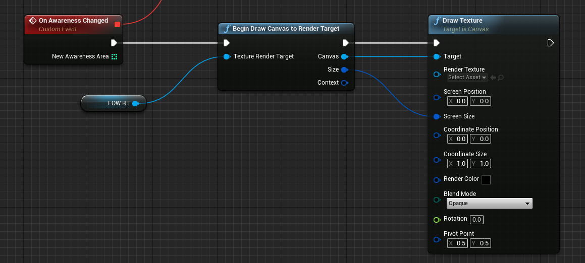
Next we're going to draw into the canvas. The first thing we'll do is clear the canvas with black, because we'll be calling this over and over so we want to draw on top of the last frame's information. Note that if you leave Render Texture empty in that slot, it will just draw a solid color, which is what we want.
We loop through each tile index and convert this to grid coordinates. Like I've explained above, index = x + y * width, so we can extract the X and Y out. For now we leave the Z alone.
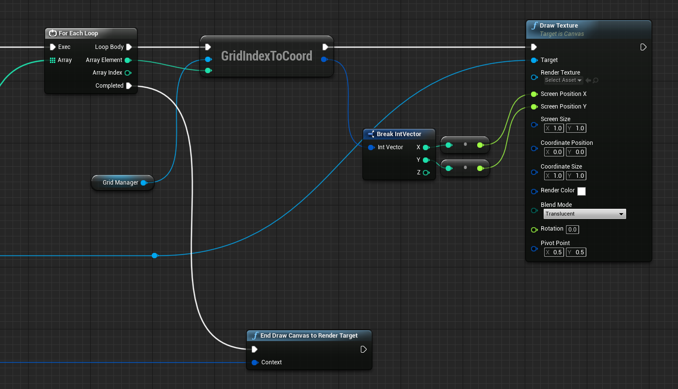
Here we draw a single pixel at the exact X and Y coordinate. Setting Screen Size to 1.0 will draw 1 pixel perfectly into the canvas.
Finally we end the canvas drawing which marks the canvas as ready to be displayed.
If we examine the canvas render target, we can see it rendered some pixels. The white part now represent the fog of war visible area. You can see the changes when we update our map.
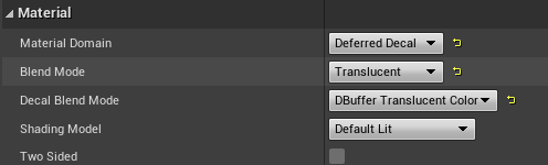
Fog of war Decal Material
To display the fog of war, our solution is to use a map-wide decal. In Unity this is the same as using a Projector. The performance characteristics of decals is equivalent to one extra draw call, so this is a pretty cheap way to do it.
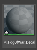
We're going to make a new decal material like so, add it as a decal to the level, and make it cover the entire map.
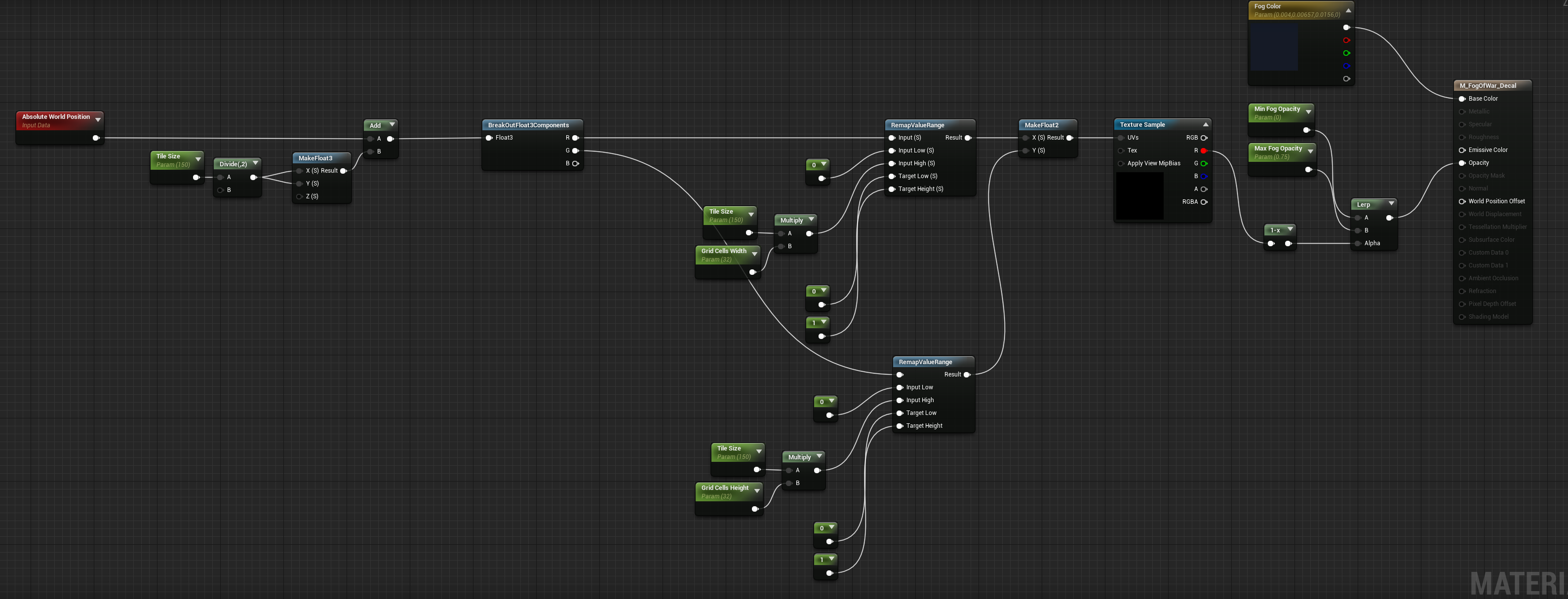
In the decal material our goal now is to figure out how to get from the absolute world space position of the pixel to the corresponding pixel of the the canvas.
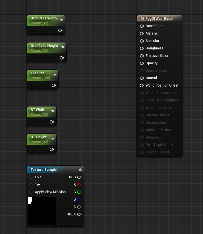
First we'll need to give the material some outside information. We need the grid cells width, height, and the tile size physical dimensions.
We'll also need the dimensions of the render target. And ofcourse the render target itself, which can just be referenced directly.
Let's review what's happening with Absolute World Position on a material like Decal.
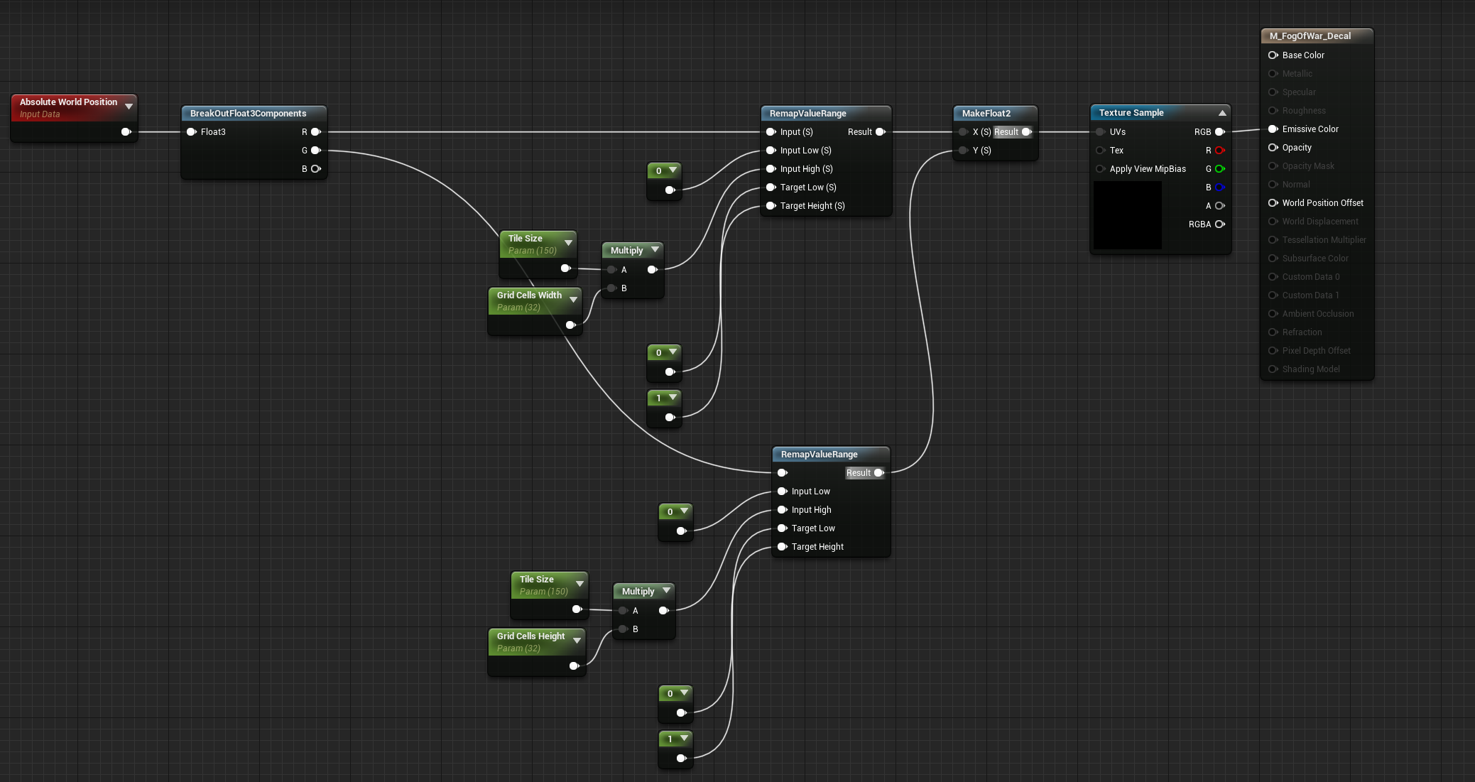
Absolute position to grid canvas position
For every pixel we'll know the Absolute World Position of that pixel. If we render it like this, where we mask component R (only the X axis), and remap it's expected range within the level (0 to tile size * grid width) to 0-1 range, we see this.
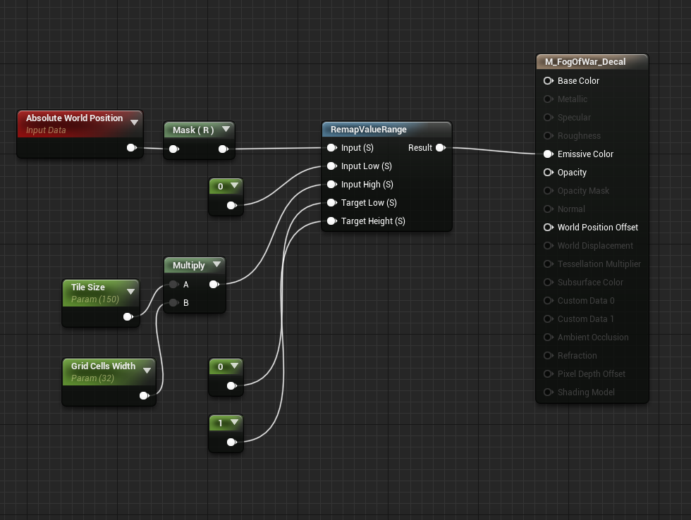
You can see it the shade go from black to white as X value increases. Same with Y axis.
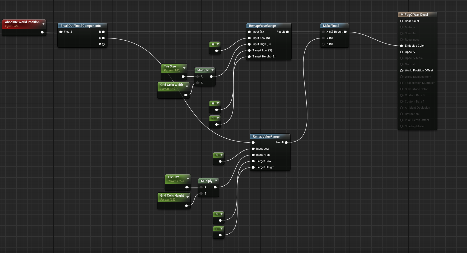
Now if you map both axes independently and into the red and green channel you can get something like this.
Instead of outputting a color, we use these normalized coordinates to sample the canvas render target we rendered to earlier. This will give us something like this.
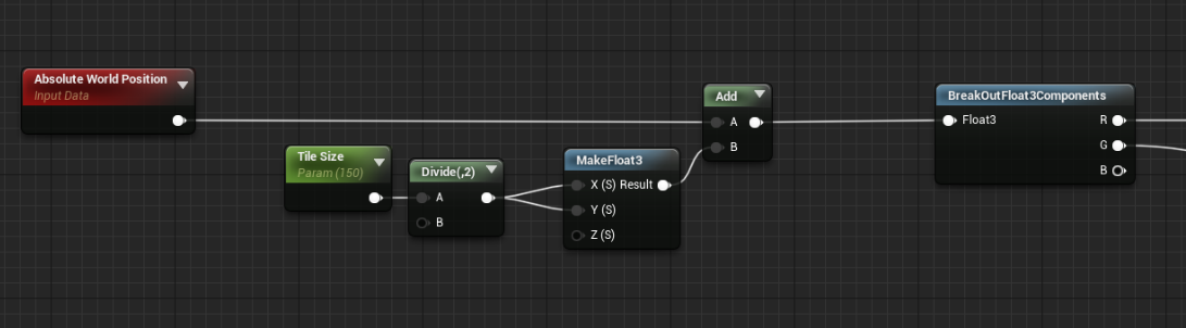
Here we have a slight problem. Grid coordinate space in my game begins at 0,0,0 for the top left tile, but that location points to the middle of the tile, not the corner. 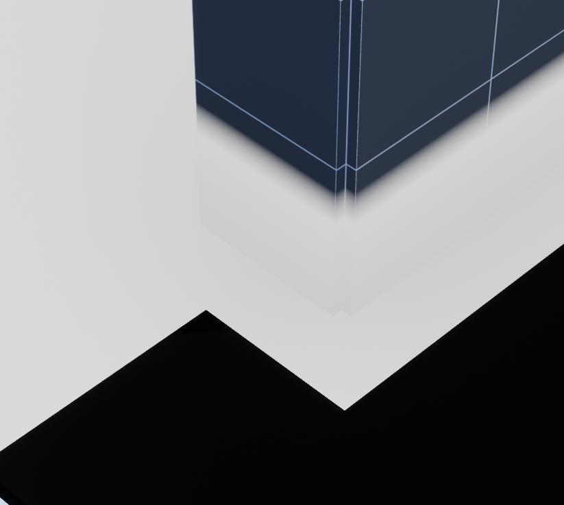
An easy fix for this is to simply offset the absolute world position by half a tile.
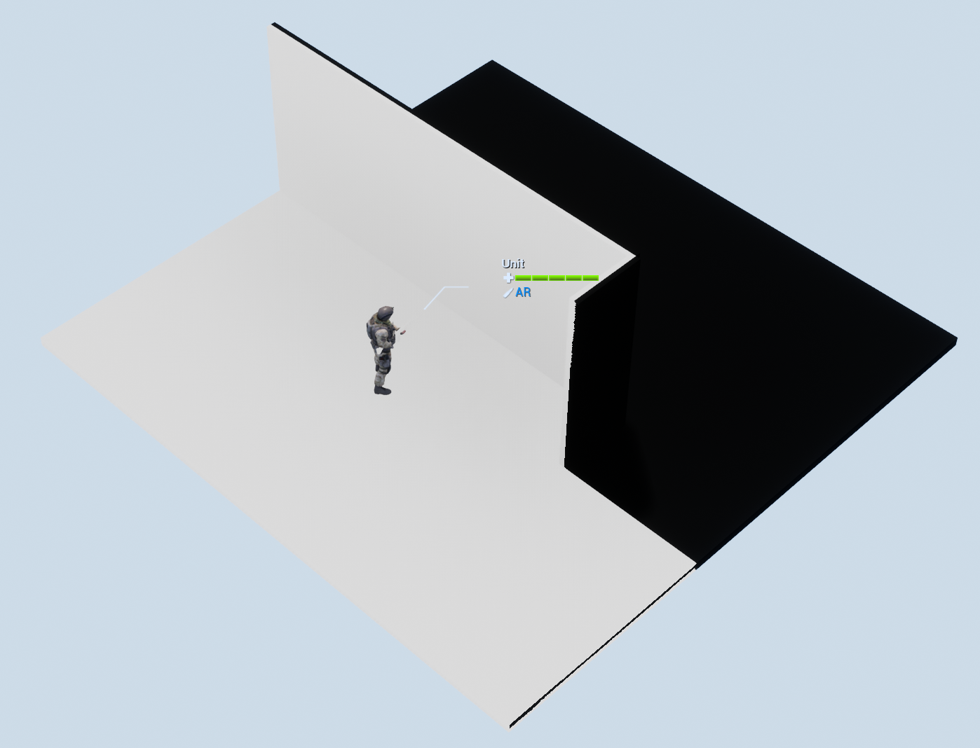
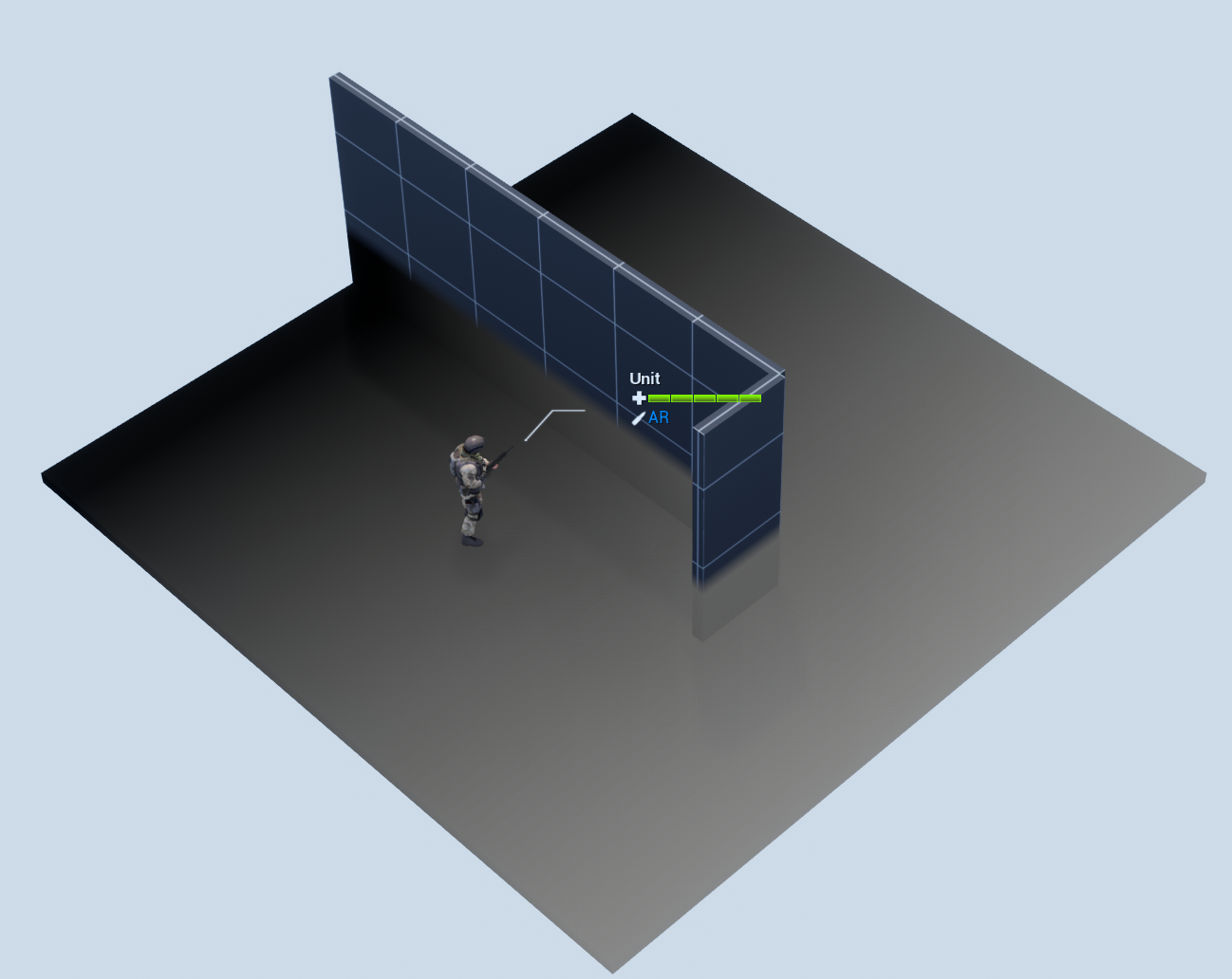
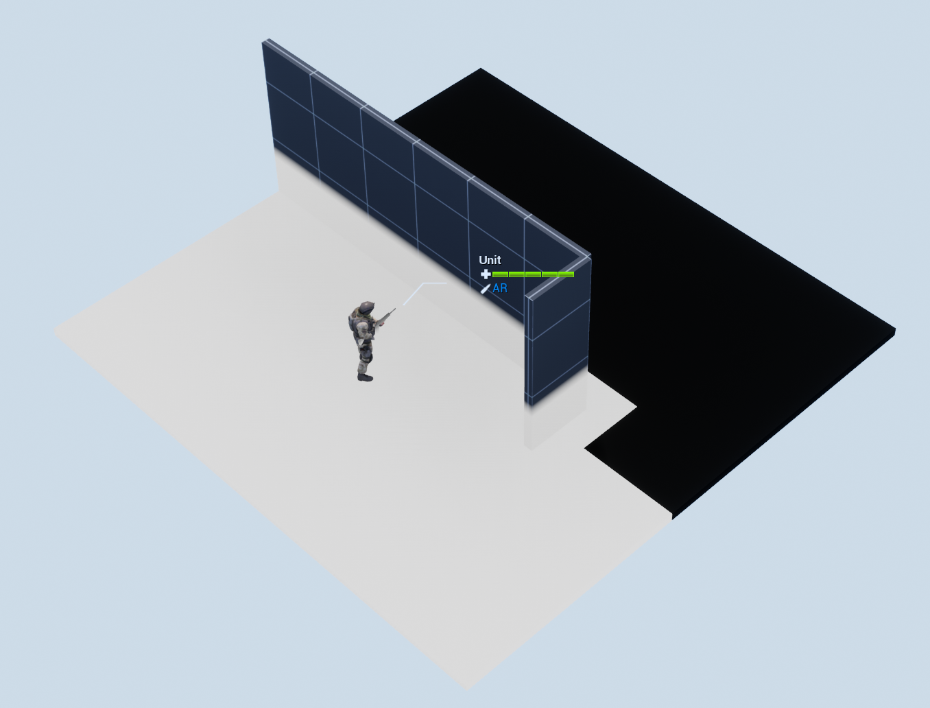
Making it look good
Now, we want to inverse the effect of the material. Non visible areas should be darkened, while visible areas should be normal.
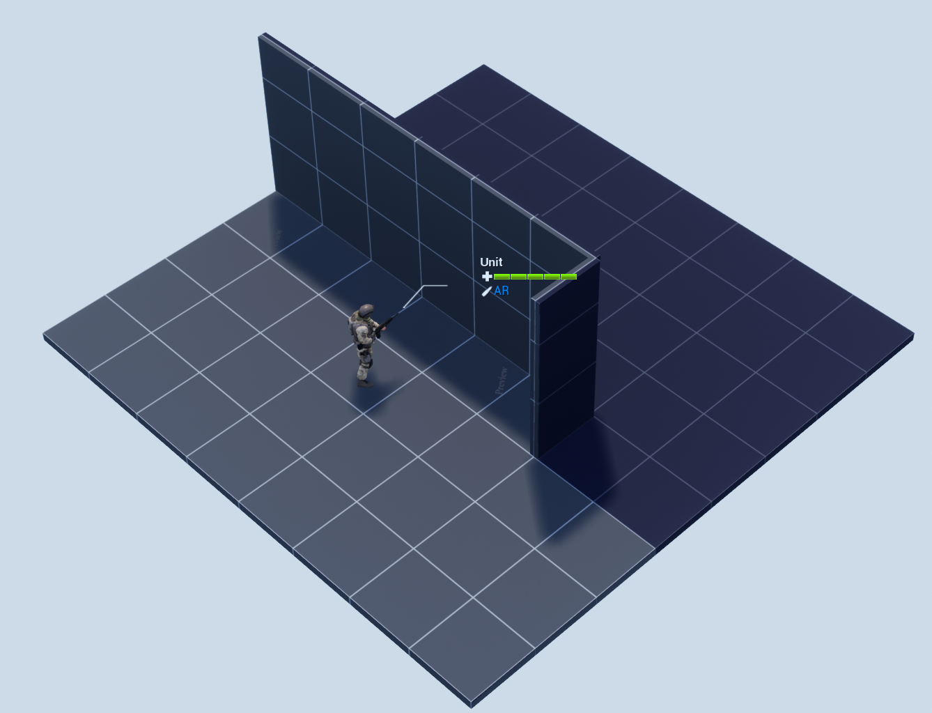
To make the fog of war blurry, we can simply change our mip settings to something other than Unfiltered.
Note that while this is very cheap to do, it can cause fog of war to bleed incorrectly beyond thin walls.

Fading fog of war over time
To fade the fog over time. we can make a second render target, and paint the first one slowly into it over time.
Here I simply cloned the original fog of war render target to a new one.
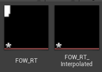
This is also added as a reference in the fog of war BP.

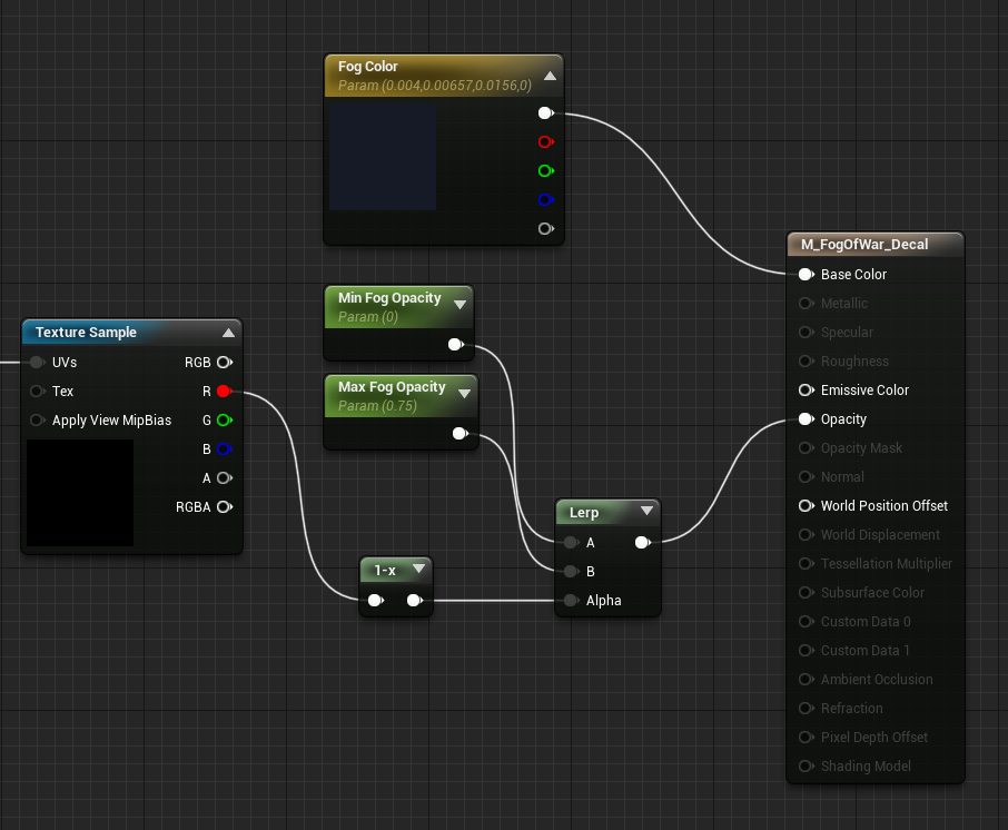
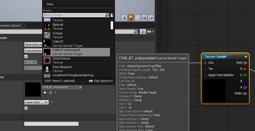
Then in the fog of war material I replaced the texture sample with the interpolated version of the render target.
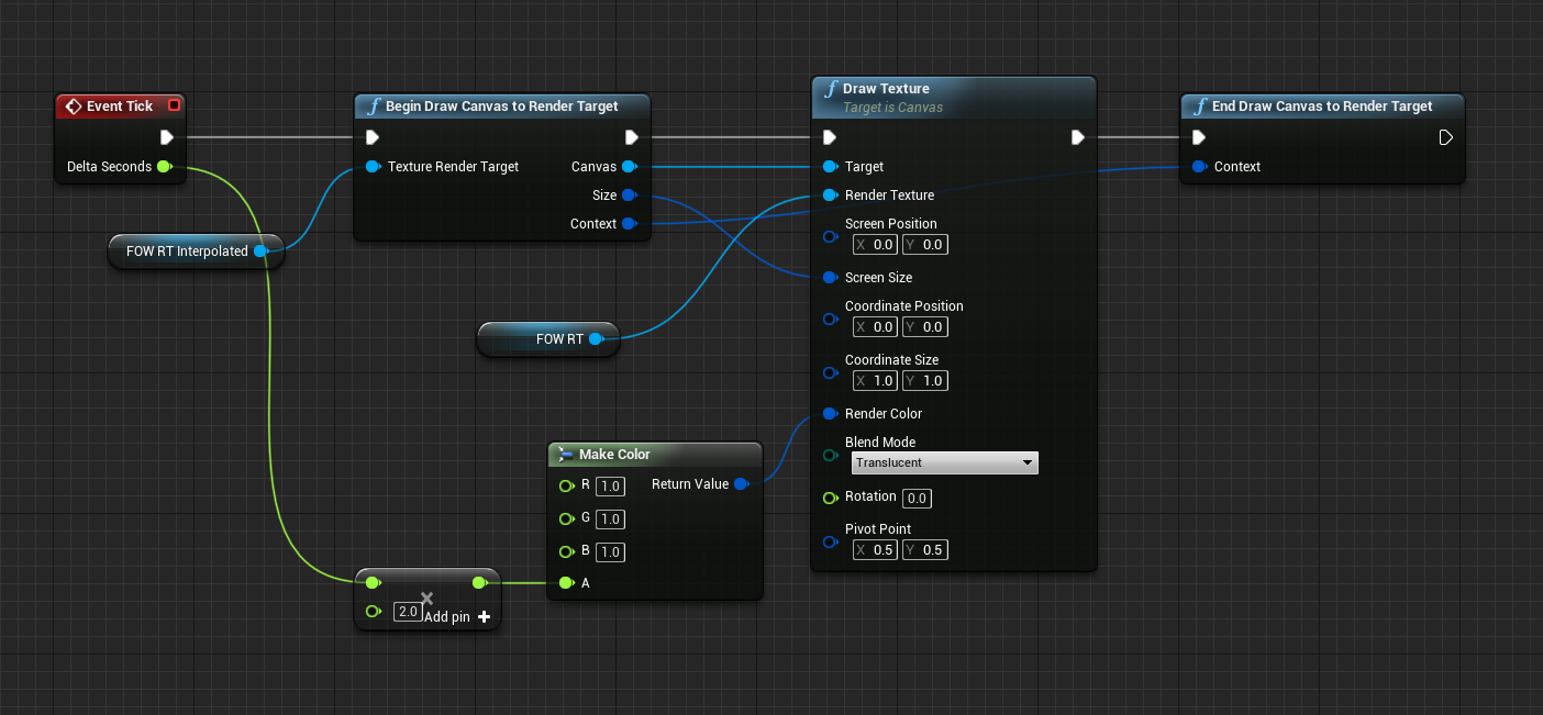
For the fog of war BP I added a tick function that draws the original fog of war canvas into the interpolated canvas, but with a low alpha that is based on delta time.
Conclusion
For reference, here are the material and actor BPs.
In the next part I'll go over how to extend this to multiple floors, as well as some tips on cleaning up the overall look. Hope this helps!
Comments
Log in with itch.io to leave a comment.
we really need a part 2 pleeeease
Did you ever write a part 2? Or specifically, how would you tackle the multiple floors?
How do you have the initial fog of war initially pitch black, then once you explored the area it has the darkened out fade area?